Do you dare to design a Suspension Bridge? It is an ultimate dream!! Many structural engineers dream to evolve a design of at least one Suspension Bridge which would be a national landmark bringing prestige and fame to a country where they belong. Suspension Bridges are economical for main span (central distance between the Pylons or Towers) beyond 500m. For your reference, listed below are the top 12 longest Suspension Bridges of the world in ascending order but there is stiff competetion amongst countries to topple one another for the top position. Just imaging the length of main span constructed so far and opened for traffic as a marvel. Chinese bridges are listed in 6 amongst top 12 suspension bridges in the world. Just Google to find out more information about them.
#12. Yavuz Sultan Selim Bridge, Turkey: Width 58.4m, Main Span 1408m, Year Opened 2016
 |
| Yavuz Sultan Selim Bridge, Turkey |
#11. Humber Bridge, United Kingdom: Width 28.5m, Main Span 1410m, Pylon Height 155.5m Year Opened 1981. Engineers constructed the bridge's spans by suspending them from hollow reinforced concrete towers 155m high. The Humber was the first major suspension bridge to use concrete in this way where other bridges used steel towers. The cables that hold the deck are 700mm in diameter and weigh 5,500 tonnes each. Each cable is made up of 37 strands of 404 lengths made of high tensile galvanised steel wire. Galvanised wire has been protectively coated with zinc.
 |
| Humber Bridge, United Kingdom |
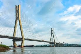
#10. Fourth Nanjing Yangzte Bridge, China: Main Span 1418m, Pylon 229m, Year Opened 2012
 |
| Fourth Nanjiang Yangtze Bridge, China |
#9. Second Dongtinghu Bridge, China: Main Span 1480m, Pylon Height 206m, Year Opened 2018
 |
| Second Dongtinghu Bridge, China |
#8. Runyang Yanstze Bridge, China: Main Span 1490m, Pylon Height 207m, Year Opened 2005
 |
| Rungyang Yanstze Bridge, China |
#7. Yi Sun-sin Bridge, South Korea: Main Span 1545m, Pylon Height 270m, Year Opened 2012
 |
| Yi Sun-sin bridge, South Korea |
#6. Osman Gazi Bridge, Turkey: Main Span 1550m, Pylon Height 236.4m, Year Opened 2016
 |
| Osman Gazi Bridge, Turkey |
#5. Great Belt Bridge, Denmark: Main Span1624m, Pylon Height 254m, Year Opened 1998
 |
| Great Belt/Storebaelt Bridge, Denmark |
#4. Xihoumen Bridge, China: Main Span 1650m, Pylon Height 211.3m Year Opened 2009
 |
| Xihoumen Bridge, China |
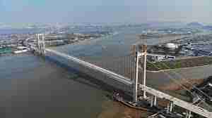
#3 Nansha Humen 2nd Bridge, China: Main Span 1688m, Widt 49.7m, Year Opened 2019
 |
| Nansha Humen 2nd bridge, China |
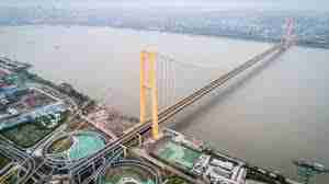
#2. Yangsigang Double Deck, China: Main Span 1700m, Pylon Height 231.9m/254.9m Year 2019
 |
| Yansigang Double Deck Bridge, China |
#1. Akaski Kaikyo Brdge, Japan: Main Span 1991m, Side Span 960m Pylon Height 282.8m above sea level, Year Opened 1998, Cost 500 billion Japanese Yen. Withstand wind at 290km/hour and earthquake at 7.5 Richter scale. The longest, the heighest and the most expensive suspension bridge in the world.
The total weight of the super-structure is distributed as follows: 46200t steel tower, 57700t cables, steel beams 89200t. The length of the cables used in the bridge amounts to 300,000 kilometers, enough to circle the earth 7.5 times. Two main Steel cables each with a diameter of 112cm contain 36,830 lines of 5.23mm wire diameter in 127 / 290 (stranded wire / cable wire) construction
 |
| Akashi Kaikyo Bridge, Japan |
Tricks for Design of Suspension Bridge
Before we can proceed with the designing of the structures, it is necessary to find the most favorable solutions of the following problems:
1. The choice of wire-cable mterial with regard to corrosion protection and strength: Locked Coil wire Ropes are preferred otherwise galvanised wires with zinc coating are also used.
2. The economic ratio of cable-rise to length of span.
3. Choice of depth of stiffening truss and its's material. The best ratio of depth of stiffening truss to length of span to keep deflections within permissible limits due to effects of live load, wind, earthquake, and temperature.
4. Choice of Pylon/Tower and it's material
5. Anchorage for main cables at side spans.
However, we will restrict our discussion on geometry, main cable, and suspender cable design with a schematic example.
Geometry Optimisation:
Assume that there would be two cable planes near the ends for supporting the full carriageway width comprise of car lanes, rail tracks, cycle tracks, footpaths etc. Vertical dead load , live loads are to be shared equally by two planes of cables, suspenders and stiffening truss. The cables are passed over the head of Pylon /Tower and anchored separately after the suspended side spans on both sides.
#1: In the absence of any governing conditions, both the side-spans(ls) will be assumed one-half the length of the main span (l), ls=0.5l So horizontal suspended length of bridge is 2l.
#2: The economic rise to span ratio for main calble lies between 1/6.9 to 1/8.7 for having two side spans. So Keep cable Rise to Span ratio (f/l) = 1/8 (= 0.125) for main span and the same rise to span ratio of 0.125 for both suspended side spans ie fs = f/4. The total length of main cable becomes L = 2.11l. When there is no side span, economic rise to span ratio (f/l) should be chosen as 1/9.
#3. With side span (ls) as 0.5l on either side of Pylon,this ensures equal inclination of cable on either side at tip of Pylon/tower.Each tower will consist of one boxcolumns, one pylon for each cable system, rigidly tied together by transverse bracing in a vertical plane.
#4. In nearly all of the above bridges, a stiffening truss is the means employed to prevent the deformations due to live-load, wind, earthquake and changes of temperature. If d is the depth of stiffening truss, then (d/l)minimum = 0.0222 or 1/45. A good start is with d/l = 0.025 or slightly higher value probably because most designs have been a compromise between the demands of economy and those of aesthetics. The stiffening truss/girder be desidned only for live load moment M= pl^2/60 where p is the equievalent distributed live load for the full span.The stiffening girder depth is a very important factor for the design of suspension bridge. Just like cables there would be two planes of stiffening truss to resist live load bending moments. The steel material for stiffening truss may be High Tensile Steel Fy 350MPa or more provided rail tracks ar laid between trusses with appropriate coushions to minimise fatigue.
#5. The following considerations indicate that the safety factor for cable material may be judiciously reduced as the span is increased:
- On a longer span it takes more time for a maximum load to come upon the bridge, so that the application of stress is more gradual.
- On a longer span with the same traffic, the combination of loads producing maximum stress will be much rarer in occurrence.
- As the span increases, the deadload becomes a greater percentage of the total load, so that the range of stress variation in the cable is diminished.
- The resistance of tension members to suddenly applied stress increases with their length, on account of the increase in the resilience of the members.
- It is reasonable to expect some improvement in the cable material before the larger spans are built. Furthermore,the best material can be afforded in the largest spans.
Schematic Example: Choice of cable section of a 1000m main span Suspension Bridge:
Geometry:
Main Span l = 1000m Side Span ls = 0.5l = 500m Sag to span ratio in main span f/l = 0.125 So f= 125m, sag to span ratio in side span fs= f/4= 31.25m
Depth of Stiffening Truss d =0.025l = 25m (suitable to accommodate rail on lower deck and road traffic on upper deck). Stiffening truss hinged at Pylons and connected to main cable with suspenders at 10m..
Panel length between verticaal suspenders for truss with main cable, a = 10m
Total Roadwidth for 3lanes To & Fro traffic plus cycle tracks on both sides = 25m. These are also the planes of main cables and stiffening truss and lateral pylon centers.
Pylon/Tower Height= f+d+ship clearance = 125m+25m+50m(approx) = 200m
Inclination of cable at Pylon head with horizontal alpha= 14.036deg
Loading:
2 railroad tracks at eudl of 50kN/m = 100kN/m (1 lane each to & fro on lower deck)
6 lanes of highway automobiles (6 lanes on top deck) at eudl 15kN/m = 90kN/m
Total LL P= 190kN/m
25m roadway dead load plus stiffening truss eudl 20kN/m = 500kN/m
Self Weight of Cable and Suspenders = 20kN/m
Total DL G = 520kN/m
Total congested DL+LL , G+P = 710kN/m
Main Cables:
Main Cable Maximum Horizontal Thrust H = 0.50(G+P)l = 357500 kN as there are two cable planes.
Main Cable Maximum Tension T = H.Sec(alpha) = 368225kN
Select Wire Ropes breaking strength of futs = 1570MPa, Area Required = 703615mm^2 wth factor of safety of 3 for structural wire rope. No of 7mm wire strands required = 18285 nos
Select on each side: Two cables of 37 strands, each strand containing 248 wires of 7 mm diam. Total Nos = 18352 ok.
There should be some margin kept in cable strength for temperature stress and wind effect.
Suspender Cables:
Load on suspender cable on each side = 0.5x10x710 = 3550kN
Select One Locked Coil Wire Rope 100mm dia for suspenders @ 10m centers to hold stiffening truss
Recommendation
The above writing is meant to inspire upcoming structural engineers who are fearless to explore the opportunities of designing suspension bridges. Hope this information would serve as an aid to structural engineers and decision makers to explore feasibility of suspension bridge with more zeal and confidence. The author has no conflict of interest and the opinions are of his own.
Disclaimer
The contents of this article is for informational purpose only and proper professional guidence must be sought before implementation of design and construction of suspension bridges.

Comments
Post a Comment